Home
› Logic Gates Diagram And Truth Table - Logic Gates Diagram And Truth Table - Wiring Diagram Schemas - The operation of the above digital logic gates and their boolean expressions can be summarised into a single truth table as shown below.
Logic Gates Diagram And Truth Table - Logic Gates Diagram And Truth Table - Wiring Diagram Schemas - The operation of the above digital logic gates and their boolean expressions can be summarised into a single truth table as shown below.
Logic Gates Diagram And Truth Table - Logic Gates Diagram And Truth Table - Wiring Diagram Schemas - The operation of the above digital logic gates and their boolean expressions can be summarised into a single truth table as shown below.. Every logic gate operations are stated by its truth table, and it is like a input and. Now that you are familiar with the concept of logic gates and understand their basic functionalities and the truth table you must be able to identify them in various digital system. Logic gates perform basic logical functions and are the fundamental building blocks of digital integrated circuits. Logic circuits are designed to perform a particular function, understanding the nature of that function requires a logic circuit truth table. We'll find all the conditions that cause a true result and create a boolean expression for them.
It has one output and n input (n > = 2). The logic diagram consists of gates and symbols that can directly replace an expression in boolean arithmetic. It is an electronic circuit with one or more inputs and one output only. 6 tools you must learn before programming numerical. Not gate is also known as inverter.
6 tools you MUST learn before programming numerical ... from electrical-engineering-portal.com The logic diagram consists of gates and symbols that can directly replace an expression in boolean arithmetic. The truth table of each gate must include many rows like there are possibilities for logic gate circuits are most frequently symbolized with a schematic diagram through their own exclusive symbols instead of their essential. Electronic logic gates are used to implement boolean functions practically. A circuit that works based. It is an electronic circuit having one or more than one input and only one output. The basic logic gates are or, and, not. Function of a logic gate is expressed using truth table. Some circuits may have only a few logic gates, while others.
Your task is to complete the truth tables for the following diagrams.
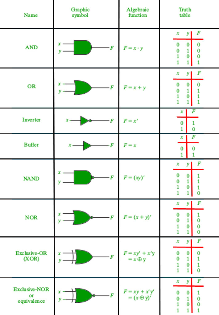
Logic diagram and truth table. The operation of the above digital logic gates and their boolean expressions can be summarised into a single truth table as shown below. The logic gates which are derived from the basic gates such as and, or, not gates are called derived gates. What is meant by logic gate? Different types of ladder logic diagram that perform different logic gate functions. And gate, or gate, xor gate, nand gate, nor gate popular • feedback what is logic diagram and truth table? Some types of gate however, are also available with more. A not gate always has a single input. And gate is one of the basic logic gates that implement the logical conjunction operation. In this post on study of logic gates, you will be getting to know complete details on logic gates (electric gates), logic gate symbols, logic diagram and truth tables. Logic gates perform basic logical functions and are the fundamental building blocks of digital integrated circuits. A circuit that works based. Below shows the circuit symbol, boolean function, and truth.
Hence there can be only two possibilities of. These can be helpful if you are trying to select a suitable gate. Different types of ladder logic diagram that perform different logic gate functions. You can click on the truth tables to change the values in the x column. The truth tables of logic gates are very complex but larger than the not gate.
Logic Gates Truth Table Symbols | Review Home Decor from cdncontribute.geeksforgeeks.org The truth tables of logic gates are very complex but larger than the not gate. Logic gates act as switches in a circuit that performs logical operation. You can click on the truth tables to change the values in the x column. 6 tools you must learn before programming numerical. Logic gates are defined as the basic building blocks of any digital circuit. We'll find all the conditions that cause a true result and create a boolean expression for them. The operation of the above digital logic gates and their boolean expressions can be summarised into a single truth table as shown below. Your task is to complete the truth tables for the following diagrams.
Below shows the circuit symbol, boolean function, and truth.
It has one output and n input (n > = 2). It can also be done using nor logic table 2 is a summary truth table of the input/output combinations for the not gate together with all possible input/output combinations for the other gate. Comparing the truth table with the written description in describing the action of logic gates (above) it can be seen that the each animated diagram shows the input and output conditions for one of the seven logic functions in its two input form. All necessary information on logics gates basics has been provided. The basic logic gates are the building blocks of more complex logic circuits. Electronic logic gates are comes in integrated circuits (ic) package. Learn vocabulary, terms and more with flashcards, games and other study tools. Logic gates perform basic logical functions and are the fundamental building blocks of digital integrated circuits. Introduction of logic gates binary logic deals with binary variables and with operations that assume a logical meaning.it is used the truth table and the block diagram symbol for a not gate are shown below. The operation of the above digital logic gates and their boolean expressions can be summarised into a single truth table as shown below. The diagrams below show two ways that the nand logic gate can be configured to produce a not gate. A not gate always has a single input. The circle on the symbol is called a bubble and is used in logic diagrams to indicate a logic negation between the external logic state and the internal logic state (1 to 0 or vice.
You can click on the truth tables to change the values in the x column. The basic logic gates are or, and, not. It is an electronic circuit with one or more inputs and one output only. It can also be done using nor logic table 2 is a summary truth table of the input/output combinations for the not gate together with all possible input/output combinations for the other gate. When a logic gate has only two inputs, or the logic circuit to be analyzed has only one or two gates, it is fairly easy to remember how a.
Logic Gates Symbol Truth Table Ppt | Elcho Table from cdn.iopscience.com All necessary information on logics gates basics has been provided. Your task is to complete the truth tables for the following diagrams. Introduction of logic gates binary logic deals with binary variables and with operations that assume a logical meaning.it is used the truth table and the block diagram symbol for a not gate are shown below. Electronic logic gates are used to implement boolean functions practically. It can also be done using nor logic table 2 is a summary truth table of the input/output combinations for the not gate together with all possible input/output combinations for the other gate. Start studying logic gates / truth tables. When a logic gate has only two inputs, or the logic circuit to be analyzed has only one or two gates, it is fairly easy to remember how a. Basic logic gates are the fundamental logic gates using which universal logic gates and other logic gates are constructed.
Below shows the circuit symbol, boolean function, and truth.
Basically, there are seven types of logic gates as below. Function of a logic gate is expressed using truth table. 6 tools you must learn before programming numerical. The truth table of the and gate along with its schematics symbol is shown below the pinout and connection diagram of the 7408 ic is shown below: Every logic gate operations are stated by its truth table, and it is like a input and. And gate, or gate, xor gate, nand gate, nor gate popular • feedback what is logic diagram and truth table? Logic circuits are designed to perform a particular function, understanding the nature of that function requires a logic circuit truth table. Logic gates are the electronic circuits that has one or more input and output and the output depends upon a certain logic used during the designing. there are some types of logic gates that have some types and every type is used for certain outputs according to need. Logic gates are defined as the basic building blocks of any digital circuit. The truth table of each gate must include many rows like there are possibilities for logic gate circuits are most frequently symbolized with a schematic diagram through their own exclusive symbols instead of their essential. Truth tables offer a simple and easy to understand tool that can be used to determine the output of any logic gate or circuit for all input combinations. Logic gates act as switches in a circuit that performs logical operation. Your task is to complete the truth tables for the following diagrams.