
Intermatic T104 Wiring Diagram
Clock motor voltage and cycle must be as specified. It reveals the components of the circuit as streamlined forms, and also the power and also signal connections in between the tools.
Intermatic T104P201 instruction manual T104R201
T104 24 hour dial time switch double pole single throw (dpst) 40 amp.

Intermatic t104 wiring diagram. Intermatic t104r wiring diagram 16.04.201916.04.20192 commentson intermatic t104r wiring diagram line 2. T104 24 hour dial time switch double pole single throw (dpst) 40 amp. The t series mechanical time switch has proven it can stand the test of time.
Following trying to remove, replace or repair the wiring in an. T104 24 hour dial time switch double pole single throw (dpst) 40 amp. Use solid or stranded copper only wire with insulation to suit installation.
Get recommended intermatic products to use when replacing another manufacturer's product. The misfortune in fact is that every car is different. Use solid or stranded copper only wire.
To my pump, i have a black, red and green wire. Product width (in) 6 1/2: It shows the components of the circuit as simplified shapes and the power and signal friends in the midst of the devices.
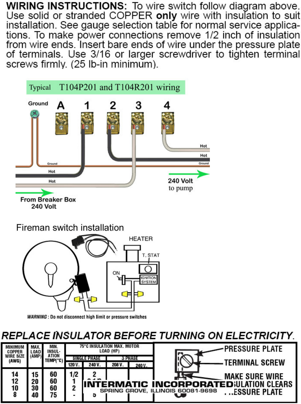
Effectively read a electrical wiring diagram one offers to know how typically the components inside the system operate. T104 poles 1 and 3 are 240 source and poles 2 and 4 go to pump motor. Operating temperature max (°c) 54:
Wiring instructions:to wire switch follow diagram above. Wire size min #14 awg: Assortment of intermatic timer t104 wiring diagram.
Any help would be appreciated. To my salt converter, i have a black, pink and green wire. Unique t104m timer wiring diagram white neutral wire famous pool.
T & t are volt timers; Intermatic t 104 wiring diagram these dependable time switches can handle electrical loads up to 40 a per pole and allow for up to 12 on/off operations per day. Wire size max #8 awg:
Intermatic timer t104 wiring diagram. To wire switch follow diagram above. A wiring diagram is a simplified standard photographic depiction of an electric circuit.
Wiring diagram 240 v 2 wire and ground clock motor: T, t & t are volt timers. Product height (in) 10 1/8:
Product depth (in) 3 5/8: The t series mechanical time switch has proven it can stand the test of time. Not clearly shown on the pic but the 120v clock motor must be connected between terminal a and terminal 1.
Operating temperature max (°f) 130: Get intermatic timer t104 wiring diagram sample. Assortment of intermatic timer t104 wiring diagram.
Wiring diagrams february 01, 2022 00:07. If your timer is 240v, or the t104 model, it will have 5 brass screws (terminals) underneath the plastic insulator cover. The time switch shall provide a minimum on/off time of 1 hour.
Use solid or stranded copper only wire. By vallery masson on august 2 2021. On this website we recommend many designs abaout intermatic t wiring diagram that we have collected from various sites home design, and of course what we recommend is the most excellent of design for intermatic t wiring wiringall.com you like the design on our website, please do not hesitate to visit again and.
Intermatic t104 wiring (simple terms) i am trying to wire an intematic timer model #t104 to my pool pump. Time pointer time dial off tripper manual lever on tripper typical wiring diagram clock motor 120/240 volt 3 wire supply to loads ground line 2 line 1 a 2 4 gr. "a" and 1 and supply neutral to terminal "a".
Intermatic t basic wiring diagram, t timer volts or volts check label on side of water heater for volts & watts this timer. Wiring instructions:to wire switch follow diagram above. Check out the diagram below, or see the wiring diagram which comes with a new timer, or is printed on the door of the timer box.
To wire switch follow diagram above. To order replacement, indicate part no. A wiring diagram is a streamlined traditional photographic depiction of an electrical circuit.
T104 intermatic 250v time clock. Swimming pool timer wiring diagram. Operating temperature max (°c) 54:
It reveals the components of the circuit as streamlined forms, and also the power and also signal links between the gadgets. / volt connect motor leads to terminals. Use solid or stranded copper only wire.
Assortment of intermatic timer t104 wiring diagram. Lr ul moving the clock hands can damage the timer. Wire size min #14 awg:
Wire size max #8 awg: I have a black wire, a red wire, and a green (ground) wire. The switch is wired to the timer.
Apr 21, 2009, 01:48 pm. Grässlin uk connect wiring in accordance with wiring diagram.

Diy water, Diy water heater
How to wire Intermatic T104 and T103 and T101 timers

How to wire Intermatic T10404R


Intermatic Timer T104 Wiring Diagram Download
How to wire Intermatic T104 and T103 and T101 timers


Intermatic T104 Wiring Diagram Wiring Diagram

Get Intermatic Timer T104 Wiring Diagram Sample

Intermatic Timer T104 Wiring Diagram Download

Wiring Diagram For T104 Timer schematic and wiring diagram
Intermatic T104 Pool Timer Off Tripper Turns Off The Clock Community Forums

Wiring Diagram For T104 Timer Wiring Diagram Schemas

How to wire Intermatic T104 and T103 and T101 timers


Get Intermatic Timer T104 Wiring Diagram Sample
Intermatic T104 Wiring Diagram
Intermatic T104 Wiring Diagram
How to wire Intermatic T104 and T103 and T101 timers


Intermatic Timer T104 Wiring Diagram Download
How to wire Intermatic T104 and T103 and T101 timers


Intermatic Timer T104 Wiring Diagram Download
